Room to investigate
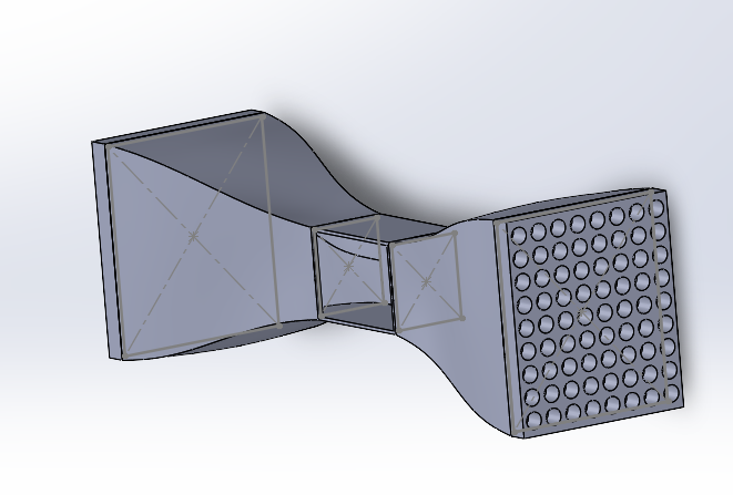
I expanded the housing to create more room for test specimens and future experimental setups.
Personal engineering project · Janbert Marania
Desktop Wind Tunnel
An independent wind tunnel project designed to make airflow visible and aerodynamic behavior measurable.
Loading the 3D assembly…
Drag to rotate · Scroll or pinch to zoom
Keyboard: focus the model, then use arrow keys to rotate, + / − to zoom, and Home to reset. Exploded spacing is for viewing the parts.
01 · The idea
I’m developing Slipstream as a platform for aerodynamic experimentation. What began as a desktop concept has grown into a project that connects mechanical design, additive manufacturing, and experimental measurement.
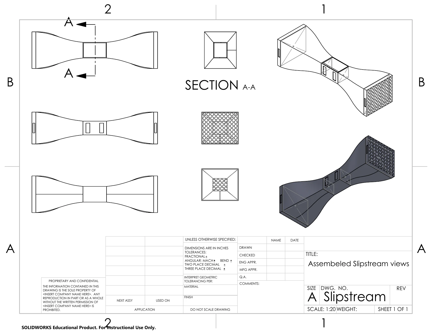
I developed the assembly in SolidWorks and documented the design through an engineering drawing. The next phase will bring the design into physical form, with airflow visualization and calibrated instrumentation planned to connect observed flow patterns with measurable data.
02 · Design decisions
I expanded the housing to create more room for test specimens and future experimental setups.
Recesses on the underside provide mounting locations for supporting and securing the tunnel.
The inlet holes are intended to help straighten incoming airflow. Flow uniformity and turbulence will be checked after assembly.
03 · Planned experiments
I plan to use fans and vents aligned along the tunnel to drive airflow through the test section. A small fog machine will help visualize how the air changes direction around different surfaces.
A mass airflow sensor is planned to quantify air passing through the system. Additional instruments are planned for airspeed, drag forces, and deflection, with calibration and test-section measurements forming the next stage of development.
Airflow sensing will characterize the tunnel’s operating conditions. Drag will need a separate force measurement, and the inlet’s flow quality will be assessed through testing. The measurement system is still being developed.
Technical context: NASA on flow straightening · NASA on drag measurement.
04 · Current progress
The SolidWorks assembly and engineering drawing document the current design. Full printing and assembly are still ahead, followed by integrating the fans, fog system, and measurement tools.
Build photographs and test results will be added as the project develops.